A3 spot welding robot system adopts COMAU industrial robot and related equipment
2021-07-11
The A3 model is a strategic transformation model of Chery. In order to create a five-star safety quality, more stringent quality requirements are imposed on the model. The increase in the manufacturing level of welded body relies on advanced Welding Equipment. The company introduced the production line of Comau to complete the welding tasks of the lower body and the body assembly to meet the higher welding quality requirements.
The first part A3 automated production line design program
Mainly responsible for the production of the white body assembly of the A3 sedan and the A3 hatchback. The lower line and the main welding line are mixed-line automatic production lines with an annual production capacity of approximately 200,000 vehicles.
The lower part of the vehicle body completes the assembling and welding work of the engine compartment, front floor, rear floor and other assembly components to meet the high-strength welding requirements of the lower part of the vehicle body. Mainly by 27 robots to complete the welding work, parts crawling, the entire line also includes automated transport catenary, parts buffer.
The main welding line is mainly used to complete assembly and welding work of the lower part of the vehicle body, the side wall, the top cover, and the package frame. It consists of a roller bed, OPENGATE, and 31 robots.
The main welding line OP130 station is an on-line laser detection system, which is driven by four robots to carry out a laser detection system to carry out on-line detection of key points on the body size.
The second part of the electrical control system
The A3 automated production line consists of two parts: the lower body line and the main welding line. There are 5 air conveying lines. The process flow is that the engine compartment, the front floor, and the rear floor are respectively conveyed by the 3 conveying lines to the lower body line. The lower part is transported over the air to the main welding line and then transported to the adjustment line via the air conveying line.
The entire production line includes a vehicle identification system, a set of roller beds, 8 sets of gluing equipment, 62 COMAU robots, safety protection equipment from SICK, and Siemens with a CPU 416F-2 with integrated safety functions. The control part uses industrial Ethernet and PROFIBUS (field bus) connection, see figure control part schematic.
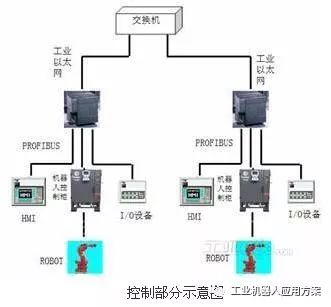
Fieldbus PROFIBUS uses the 1st and 2nd layers of the 7-layer model. The streamlined structure ensures high-speed data transmission. It is mainly used for distributed I/O equipment in the field. The PROFIBUS-DP network consists of the following components (Figure 2): 1 master controller (PLC); 2 field I/O modules (ET200S) for connecting various I/O devices; 3 other intelligent devices such as frequency conversion Devices, touch screens, etc.; 4. Network accessories (switches, etc.). It can directly complete the equipment's sequence, chain, closed-loop control, complete the collection of process parameters and alarm functions.
The following slave modules of the PLC perform hardware configuration through two PROFIBUS branches: 1. MPI network network module configuration 2. DP network module configuration. The communication between the PLC and the PLC is done through the DP/DP COUPLER. Communication between PLC and PLC is completed by DP/DP COUPLER
Two automated production lines and five air transport lines are controlled by 13 Siemens PLCs with CPU 416-2DP and CPU 315-2DP. The PLC can provide information to the system that analyzes equipment operating status and points of failure. Each production uses a Siemens man-machine interface PC870 to control, through its own MPI interface and PLC connection, internal installation of Siemens configuration monitoring software WINCC. The entire production line uses two bus modes. Communication between the PLC and the robot and between the PLC and the I/O device is via a PROFIBUS field bus. The communication between PLC and PLC adopts CP443-1 switch that Siemens produces for communication and data exchange.
The robot and man-machine interface use PROFIBUS communication protocol. The switches, solenoid valves, buttons, indicator lights, I/O slaves, etc. all use the fieldbus. Communication between PLCs in the area is exchanged via the DP/DP Coupler. Inter-zone PLC Communication via Industrial Ethernet. This bus combination method saves a large amount of wiring work, and at the same time realizes the control of the entire system, the display of process status and the display of fault alarm information, making the entire system easy to operate, easy to maintain, and highly reliable.
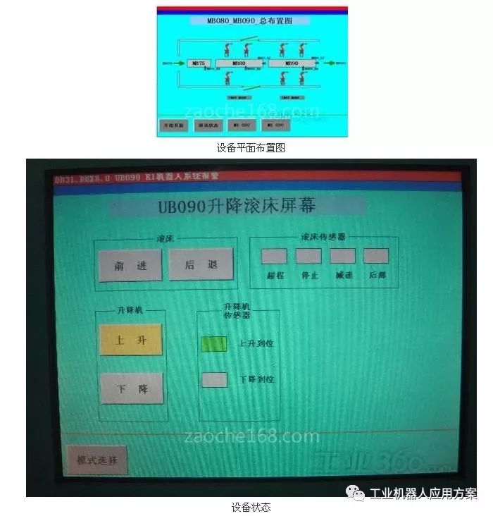
Siemens HMI provides a powerful guarantee for the operation and maintenance of the entire production line. In the robot interface through the configuration software for dynamic debugging, man-machine interface according to the operating menu is divided into station layout diagram shown in Figure 2, the state of the equipment shown in Figure 3 and so on. The man-machine interface can display the distribution status of the devices in the line and display the different states of the devices in different colors, such as running, stopping, and failure. The state of PLC and I/O can be displayed in the submenu. Figure 3 shows the fault information of the inverter () and the robot. When there is a fault, the alarm information will be automatically popped up, and the alarm information will be recorded for archiving statistics, and the historical fault record ZAOCHE168.com will be retained, which will provide reference for future maintenance and inspection equipment.
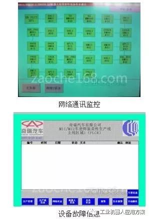
All operating interfaces use Siemens HMI, which avoids the disadvantages of traditional panel wiring, labor intensity, and inconvenient observation and maintenance. The Siemens SIMATIC product technology was successfully applied in this production line, where Profibus Fieldbus and Industrial Ethernet technologies play a key role in this system.
The third part of Spot Welding robot system
In the automotive welding process, spot welding accounts for a large part of the welding welding of complete vehicles. The welding system of the Chery A3 automated production line is mainly composed of spot welding robot system systems. The spot welding robot system includes a robot body, a robot controller, a spot welding controller, an automatic electrode grinding machine, an automatic tool exchange device, a pneumatic spot welding clamp, a water vapor control panel for water and gas supply, and the like.
The A3 spot welding robot system uses COMAU industrial robots and related equipment. These spot welding robots can automatically recognize and switch between the A3 hatchback model and the three-car model through the control system.
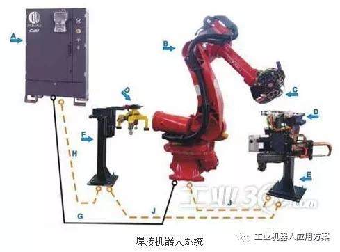
Welding robots are typical electromechanical integrated high-tech products that are powerful and easy to operate. The control method of the spot welding robot system is: The robot welding cabinet is composed of a robot control cabinet and a production line PLC Siemens control cabinet through a communication network. Spot welding controllers, automatic electrode grinding machines, automatic tool exchange devices, water and gas control panels and other devices in the robot system are controlled by robots. The robot system calls the corresponding robot welding program to carry out the body assembly welding according to the input of the host PLC signal.
3.1 Application of Intermediate Frequency Welding Technology
In order to make A3 get more excellent collision performance, in the body structure of A3, a large number of high-strength steel plates are used, and at the same time key structures such as longitudinal beams are laser welded steel plates. The traditional power frequency welding technology cannot make high-strength steel plates when welding. Get the best shear strength and fatigue resistance. In order to overcome the shortcomings of power frequency welding technology, mid-frequency welding is adopted at the lower part of the vehicle body. The BOSCH IF welding controller and the NIMAK's IF gun are used in the A3 line.
Intermediate frequency welding technology makes the excellent performance of robotic welding further improved. The advantages of intermediate frequency welding are mainly as follows: DC welding is the relative power frequency welding, the transformer is miniaturized, the response speed of current control is increased, and the welding process that can not be realized by the power frequency control can be realized. Three-phase power grid balance, high frequency power factor welding, energy-saving effect is good.
3.2 Application of gluing system
The glue coating system mainly applies spot welding sealant and isolation adhesive for the body frame. The automatic glue gun is carried by the robot, which has the advantages of high consistency of the glue track, accurate control of the amount of glue, and uniform shape of the strip after being smeared. The gluing system has provided great help for the A3 model to obtain more excellent noise reduction performance.
The glue supply system uses GRACO's high viscosity supply system. Including: 55 gallon pressure plate one and 5 gallon pressure plate, pneumatic piston pump, lifter. The fluid is pumped out and the pump outlet is equipped with dual filtration devices to filter the glue. Then connect to GRACO P-FLO LT via high pressure hose.
Feed pump adopts dual pump automatic switching mode. The equipment has automatic switching and empty barrel alarm function: a pump is in working condition and a pump is in standby state. When the glue in the working pump rubber barrel is used up, the system issues an alarm, and the automatic switching device automatically switches the working pump to another standby pump, and the standby pump becomes the working pump. The feed pump has a dual-pump switching function, which does not affect the normal operation of the automatic gluing system when changing barrels, and effectively improves the working efficiency of the production line.
The flow control adopts the United States GRACO P-FLO LT precision flow controller, including: control box, cable, fluid plate, pneumatic diaphragm pressure regulator, flow meter and so on.
The principle of GRACO P-FLO LT flow control provides the robot with an analog signal of speed. The control board controls the pressure of the pneumatic diaphragm to adjust the pressure of the glue instantly, and provides real-time accurate flow and pressure correction through the flowmeter and pressure gauge to form a Closed-loop control to achieve accurate quantitative control requirements. The gun's glue output changes with the speed of the robot.
3.3 Application of automatic electrode grinding machine
In the main welding line, in order to realize the automation of production assembly and improve the beat of the production line, each spot welding robot is equipped with an automatic electrode grinding machine, and the repair process after oxidation wear of the electrode head face is automatically completed. At the same time, it also avoids the safety hazards caused by frequent personnel entering the production line. The electrode dresser is controlled by the robot's built-in PLC and teaches a special electrode repair program to complete the electrode repair. At the same time, the welding stroke of the welding pliers is compensated according to the amount of repair.
The advantages of using welding robots: not only increase production efficiency, but also standardize the welding production process, so that product quality is stable and improved.
Part IV Other systems
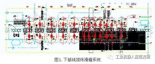
4.1 Rolling bed system
The entire A3 automated production line uses a skid conveyor for a delivery time of 18 seconds. The transportation route is: lift section conveying air-slip rake to UB10#--Rolling bed conveying--UB110#--lifting section conveying--MB10#--Rolling bed conveying--MB150#--elevating section conveying. The following figure shows the Western Line Roller Skating System.
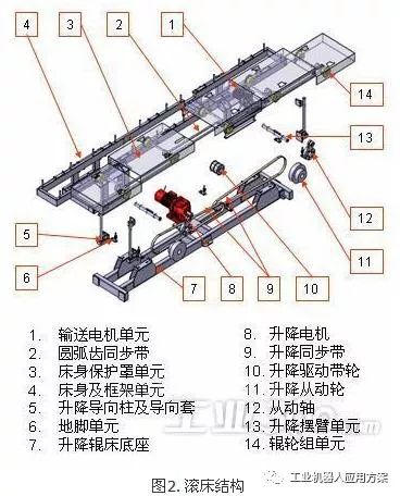
Rolling bed system structure shown in Figure 2, its working principle is: the control signal is issued, the transmission motor receives the signal, start work, slippery roller through the friction roller into the station, the sensor sensor, the transmission motor stops, lift motor receives the control signal , Begin to start, lifting and swinging arm unit drive, rolling bed begins to rise and fall, the welding robot carries on the welding after the downward positioning, after the welding is completed, the control signal sends out, lifts the electrical machinery movement, the rolling bed rises the transmission electrical machinery movement, the rolling bed rises in place, transports the electrical machinery Pneumatic, skid running and into the next station.
The M11/2 main welding line is designed for a production cycle of 100 seconds and can be used for any mixed flow of the M11 and M12 models, taking into consideration the reservation of the third model. Among them, the MB30# & MB40# & MB50# main assembly work stations occupy three stations. The format is COMAU's standard OPENGATE, which has many advantages such as high flexibility, stage investment, and easy transformation. Its own structural characteristics than the tetrahedron flip can also be used side-wall pre-installed, both sides of the welding space and other advantages.
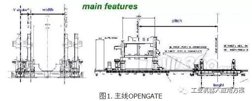
OPENGATE is the main fixture, COMAU company OPENGAT is based on the specific folder, using the door form, combined with the sensor SOOQ.cn copyright, the use of PLC control. OPENGATE and the welding robot system work together through the total control system, and finally realize the positioning, clamping and welding of the vehicle body.
OPENGATE consists of a fixture body, an air circuit system, and an induction control system. A3 main line OPENGATE body, adopts the form of the door, the base adopts the linear guide rail, carries on the direction (Y direction) movement through the thrust motor. The X-preloaded linear guides allow the vehicle to be switched, which facilitates a phased investment and improvement. The gas system uses a centralized supply of gas and consists of actuators (cylinder), control elements (valve) and auxiliary components. Sensing control system consists of electromagnetic sensors, PLC (programmable controller) and computer control system, which can realize the information acquisition and automation control of the fixture.
OPENGATE working process. Main body white body body enters OPENGATE after pre-spelling, OPENGATE body is closed, the side wall and chassis are positioned during the closing process, so that the body-in-white body pre-spelling position meets the design requirements; after positioning, the electromagnetic induction system works to check whether the positioning is accurate, if it is correct The clamping mechanism moves to clamp the body; if there is an error, the alarm system will make an alarm, OPENGATE will enter the pause state, and the control system will display the place and cause of the problem. After the problem is solved, the system will continue to work. After clamping, the sensor device checks the clamping state. If there is a problem, the system pauses and alarms. If the clamping state is normal, the welding robot starts working and welding is performed. After the welding is completed, the OPENGATE clamping mechanism opens and the gantry clamp opens. The white body enters the next process and OPENGATE waits for the next white body to enter.
OPENGATE features. COMAU's OPENGATE side panels are pre-assembled in a pre-assembled form, with side-seats joining the welding stations, side-sliding fixtures in a side-slip style, and fixtures on the side-walls of M11 and M12 share a common design. Fixtures, bases, and non-machined components in the fixture are standardized and serialized components. The tolerance between the positioning holes on the horizontal surface and the positioning holes is ±0.02mm, and the roughness is 1.6um. All the tolerances of the positioning holes and the reference surface It is ±0.05mm and the roughness is 1.6um. Fixture positioning pins and positioning block must be installed using "adjustment gasket type" structure. The positioning pin adjustment gasket thickness is 5mm. In addition, the position of the three-coordinate measurement and the machining surface are reserved in the design, and there is no need to disassemble jigs, rolling beds and other equipment during retesting.
At present, the A3 model has basically achieved the company's "2mm project." The COMAU company OPENGATE has provided a great guarantee for the "2mm" project. It has laid a solid foundation for the five-star quality of the Chery A3.
4.3 Mechanized Conveyor Catenary and BUFFER
Mechanized transport of catenary is mainly used for automatic transmission of large assembly parts, mainly engine compartment, front floor assembly, rear floor assembly transport.
The spreader on the rear floor is shared between the two models. The first-in-first-out method is used to sort parts. If the part is different from the robot, the part can be released. When the part is caught by the robot, the empty spreader returns along the return path. At the same time, it is required to have a mandatory return function. When a problem is found, the part is not forcedly returned by the capture.
Mechanized catenary parts are placed and removed by the robot.
BUFFER is mainly used for the cache of small parts. The parts are manually placed on the BUFFER and the parts are reliably positioned on the BUFFER. When the robot grabs a part, it identifies the location of the part's assembly. For example, if the part is not assembled correctly, the robot does not pick up the part and alarms. After the manual assembly is completed, press OK to release. Assembly employees need to sort parts according to the production plan. Each BUFFER is equipped with a display screen to count down the number of parts. The assembler assembles the parts according to the production plan. For some situations, such as the assembly of galvanized parts into non-galvanized board robots is not recognized.
4.4 Model Recognition and Production Management System
The automated production line integrates automatic control systems and manufacturing execution systems (MES) to form a production line management system. In the early stage, the production plan was imported into the IPC computer and the production plan for the top-level point of the individual work point was calculated through the industrial control software. Via Ethernet to the PLC. In the later period, the system was reformed, and the automation line can directly accept the production plan of the MES system.
M11 and M12 are carried out by pull-type production, and the production line receives the production plan of the MES system. Each station has a vehicle identification system based on MOBY-I. The vehicle identification system carrier is installed on each skid. Each station will automatically switch between welding procedures and welding parameters based on the information identified by the vehicle identification system.
The engine compartment assembly station is the starting point of the plan. Paste the bar code at the assembly station to determine the model information. When the stacker is placed on the transfer platform, the scanning device scans the VIN code information and sends it to the PLC control cabinet. According to the received production plan, the control cabinet determines whether the robot performs part picking. When the information is correct, the robot sends a signal to the robot, and the robot performs part grabbing. At the same time, the VIN code information is passed to the next station.
The first robot of the main welding line sets the VIN code scanning point, writes the information on the ski carrier, and transmits the production information to the next station. The second station advances the fixture and welding in advance according to the information judgment function. Parameters, welding program preparation for switching. When the sled arrives at the second station, the device reads the information on the model on the sled and checks the information read from the sled with the information transmitted from the first station. If the check is correct, the device executes the procedure. And so on.
The entire production line has 9 gripper robots. The upper robot has the recognition ability of two models. According to the production plan, the parts of the corresponding models can be selected. Once the parts are wrong or missing parts, the robot stops working and alarms, and each BUFFER is on. With vehicle identification system.
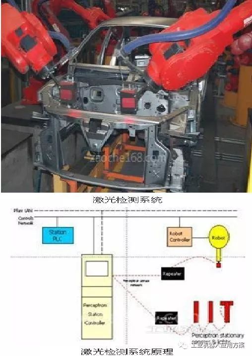
4.5 Online Laser Detection System
The main line 130 is a robot laser detection station, which is composed of four robots carrying a laser detection sensor, which is established to ensure the accuracy of the car, and detects the 252 measurement characteristic of the M11.M12 vehicle body.
The Perceptron measuring system collects the actual body size through a laser sensor on the robot. The system transmits the data to the data control station through the repeater for analysis and comparison with the standard data. The size exceeds the process range, and the data station immediately sends the PLC-controlled line failure. And alarm signals, stop the production line and prevent the unqualified body from flowing to the next process.
4.6 Security System
Hardware configuration: Siemens PLC, raster, emergency stop button, security gate, area scanner, etc. of the CPU 416F-2.
The safety-integrated input and output signals serve as interface for the process and can directly connect single-channel and dual-channel input and output signals, such as emergency stop buttons and light barriers. The safety integrated signals are internally connected as redundant signals. The use of a fail-safe distributed I/O system allows the safe engineering configuration of the system to be replaced by PROFIBUS-DP components, including replacement of emergency stop and switch devices, guard door monitoring devices, and two-hand operation.
In the program block, various safety equipments such as emergency stop, safety gate, and grating are logically controlled to replace the traditional safety relay control method; in the program, the logic processing of each safety device is mainly realized through three program modules: Raster mask data function module, emergency stop masking data function block, security gate masking data function block.
The advantages of the safety integration project integrated in the standard automation system are:
1. Automated systems with safety integration are more flexible than mechanical and electrical solutions
2. PLC-based safety systems significantly reduce wiring costs compared to traditional hard-wired systems
3. The integrated function can reduce engineering time due to system programming configuration using standard engineering tools
4. Fail-safe CPUs not only handle safety-related controls but also participate in standard automation tasks
5. Failsafe programs and standard programs can share data and communications on a unified platform
summary
The A3 automation line is a modern production line built by COMAU for Chery. In order to achieve automated production, provide various automation equipment, and organic integration, use the field bus to connect in the PLC, PLC and PLC to connect through the industrial Ethernet, to provide a lot of convenience for the use of the production line, maintenance. At the same time, the man-machine interface greatly improves the controllability of the production line and provides convenient conditions for maintenance.
COMAU's OPENGATE technology lays the foundation for realizing the "2mm project" of the car body. The proper use of medium frequency welding technology plays a key role in improving the performance of the car body. Various auxiliary automation equipments greatly increase the automation rate of the entire line.
Chery's "Ten Years of Milling" flagship and strategic model A3 has undergone groundbreaking "100,000-kilometer continuous uninterrupted public test" and "breakthrough C-NCAP five-star safety test" and has been continuously rated as " Independent brand cars." These good comprehensive performances, especially safety, are inseparable from Chery's efforts to build a fine body. The excellent quality of A3 is in exchange for a large amount of manpower, material resources, and advanced technology for design, planning, craftsmanship, and manufacturing. The automation line designed and manufactured by COMAU has played a key role in improving the superior quality of the A3 body. The A3 automation line is the product of self-owned brand cars that are aligned with international standards. The leap in quality of the A3 model has benefited from the application of automation lines, making the exploration of body welding equipment move toward a higher level.
Welding Robot are currently being widely used in the areas of defense, shipbuilding, marine technology, chemical equipment production, pressurized vessel manufacturing and nuclear power installations.
We design our products to meet the specifications of process flow, while taking into consideration the restrictions of cutting and welding. Our products are equipped to solve the numerous problems which arise in equipment fabrication, such as making accommodations for nonstandard work piece sizes and incorrect locations.
Automatic Tube-Plate Welding Robot

Scope of application
This robot is mainly designed for the welding of tube and plate on the shell and tube heat exchanger. It applies advanced vision positioning, laser vision tracking and intelligent control technologies to achieve real automatic tube-plate welding without manual operations.
Product features
• Automatic positioning and changing position: it applies advanced vision feedback technology to achieve non-contact positioning, which can avoid manual shift, insertion and extraction in mechanical positioning process. It makes the positioning process more quick and accurate.
• Laser vision measurement: it extracts the three dimensional information of the welding position automatically using laser vision system, which solves the problems caused by non-standard shape and wall thickness of the tube, and positioning error between the welding gun and the workpiece in the real production process.
• It can weld many kinds of workpieces, including steel bar, waist-shaped tube, oblate tube and some other non-circular workpieces.
•The welding head uses conventional high quality wire feeder, motion electromechanical components, which are more reliable and durable.
•Intelligent digital AC servo control system runs automatically. The operation process is easy, which can lower labour intensity and skill requirements.
| Model number | TPWR-5 | ||
| Welding material | Carbon steel, stainless steel, titanium alloy | Protective gas | Argon |
| Tube diameter | φ8~φ80 mm(customizable) | Cooling mode of the welding gun |
Water-cooling
|
| Tube position | Out of, parallel, inside of the plate | Welding gun obliquity | 0~30 degrees (adjustable) |
| Movement stroke(mm) | 1500(w) ×1800(h) ×280(z) | Welding speed | ≤12 rpm |
| Welding wire diameter | φ0.8.φ1.0mm | Equipment size(mm) | 2550×2800×1760 |
| Tungsten diameter | φ2.4~φ3.2mm | Equipment weight | 900kg |
| Welder rated current | 300A | ||
Welding Robot, Welding Machine, Head Of Welding Robot, Curved Plate Bevel Cutting Robot
Shitong Welding Equipment Co., Ltd. http://www.longxuanmachines.com